The following information provides an overview of some of the minimum requirements necessary to assist in the purchase of a communications structure designed to the ANSITIA-222-G standard. Its Not Just Line of Sight.

Flow Chart Of Proposed Antenna S Design Steps Download Scientific Diagram
Determining whether a proposed path is line-of-sight evaluating path clearances with regard to refractive effects.

. A reliable microwave link should have link availability as good as 99999. In the first two parts of this series MRT May and June the microwave path design process was described in terms of. Our microwave tower construction specialists have installed numerous varieties of microwave equipment from pressurized systems to split radio configurations used in frequency bands ranging from 25GHz to 80GHz.
Quality and availability calculations. Codal Provisions in the design of Communication Towers. The microwave design software tools are used for detailed path engineering and interference analysis.
An antenna pattern or radiation pattern is a 2D or 3D contour plot which shows the angular variation in an antenna parameter such as the relative field strength in the far-field. Analysis and Design of Transmission Tower Initial cond. October 3 2017.
Our registered certified crews are adept in all aspects of ensuring reliability and carrier-grade service. Evaluating path clearances with regard to Fresnel zones. Steel used in bridges.
Fading and fade margins calculations. K-Factor Considerations For K1 the radio horizon is longer than the optical horizon which allows shorter towers. The pattern is usually presented in polar coordinates and with a dB scale.
Planning a Microwave Link. This softwa re has nine. Performed as a part of detailed microwave system design and all the detailed hardware requirements bill of materials are defined based on this information.
Determining whether a proposed path is line-of-sight Evaluating path clearances with regard to refractive effects. At 32C 0 wind 22862 2286 K 178X10-5x262x10-4x816x109x32 09422x3202x816x109x262x10-424x12 K 1848 Put K 1848 in above equation find out tension and sag in conductor. Towers are a crucial part of a transmission line project carrying overhead lines at a safe height over the ground right from the generation plant to the load centres.
Installation of ODUs and IDUs as per link design. An example of 2D antenna pattern in an azimuthal cut. Our technicians are certified with multiple original equipment manufacturers OEM and can perform a full array of tests programming.
Due to wind loading lattice tower foundations can experience both vertical loads and horizontal loads. A preliminary fade margin is a result of the lossattenuation calculations and is. Computer aided design routines are developed for any soil conditions such as dry partially submerged or fully submerged.
Sag WL28T 22 GEOMETRY OF TOWER 1. Loads and Load Combinations. We begin our microwave service discussions with.
Artikel berikutnya DESIGN OF STEEL STRUCTURES II_TRANSMISSION TOWERS. Classification of Steel bridges. The implemented microwave planning tool is software developed to automatically design microwave point- to -po int links.
Experienced installing all types of foundations for towers and equipment buildings as well as for generators or fuel tanks. Running labeling and securing of. Frequency planning and interference calculations.
Choose an Microwave Transistor based on design specifications Design a DC Biasing circuit for desired operation. This last installment discusses path reliabilityPreceding installments in this series have described basic considerations. Class A Class B Class C or Class AB Design the Input and Output Matching Circuits based on the desired type of.
The design can be done based on Indian Standards British or American. It is recommended that you contact these leading manufacturers and suppliers for additional guidance. We acquire all materials rebar etc and.
In wet coastal areas however K can be as low as 05. K-factor of 43 or 133 is used is most cases for planning a link. Carriers and tower owners can foster a.
52 Spectrum Management 521 Availability of Spectrum. Rooftop tower or monopole locations through use of riggers crane bucket extra Installation of dish antenna on existing antenna mast. Hence foundation design and estimation of quantities forms an important and integral part in any tender final design phase in transmission or microwave tower Industry.
Lower K requires higher antennas. Design Procedure for foundation. Microwave link design is a methodical systematic and sometimes lengthy process that includes the following main activities.
Clearly defined streamlined process for responding to incidents in a timely manner. The basic design flow for this topology is as follows. Foundations are put in exactly to manufacturers specifications and any deviation needed from the original design is ALWAYS approved via the manufacturer before continuing.
The vertical loads act in both the upwards and downwards directions as the tower attempts to overturn. Introduction to Microwave Towers. Prepare criteria or a checklist for new tower approval which can be used at the countyregional level or adapted for local use.
Lauttamus offers a full menu of microwave site services starting with engineering and design and continuing on through long-term maintenance and service programs. This was the basic topology that we adhered to through our design procedure. Microwave link installation includes.
5 Key Factors for a Stable Microwave Link. Carriers and tower owners should create a standard protocol to ensure that all employees including employees of contractors report unsafe conditions on tower worksites to the carrier and tower owner. Artikel sebelumya DESIGN OF STEEL STRUCTURES II_MICROWAVE TOWERS.
Establish the traditional tower construction tower must have a process group either the whole group or sub group tower duration are similar but the basic need to set up steel rod construction process just the overall steel rod cross arm after installation set immediately available the construction speed is much faster than the Eiffel tower construction under. As microwave links can be well affected by time of day as well as many other geographical factors for critical links it would be important to have a constant test of at least 48 hours. On an average towers and their foundations account for more than half of the cost involved in the construction of a transmission line.
Types of Communication Towers. Part 4-This series of four articles is a primer on some of the propagation-related basics of microwave path design. ANSITIA-222-G TOWER DESIGN CHECKLIST.
Self-supporting towers can either utilize a single foundation supporting all of the tower legs or individual foundations below each leg. Camouflaged towers and an expedited review and approval process for towers proposed within preferred land use areas using public facilities or co-locating with other providers.
Ray2 Microwave Link 4 Installation Racom

Microwave Link Installation Alignment And Testing Dragonwave X
Microwave Link Installation Alignment And Testing Dragonwave X

Space Diversity In Microwave Links Microwave Link
2

Microwave Link Installation Alignment And Testing Dragonwave X
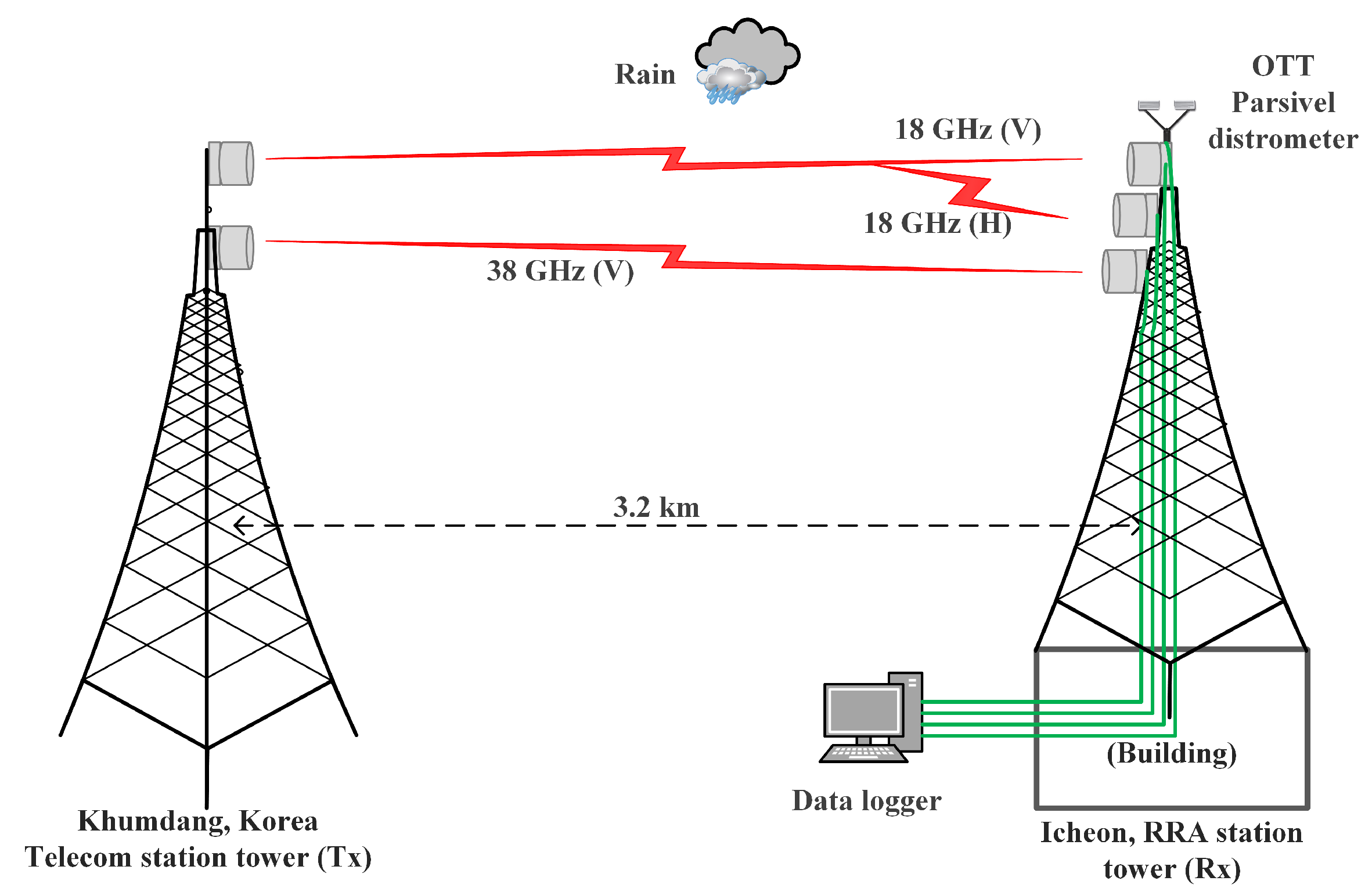
Electronics Free Full Text Rain Attenuation Scaling In South Korea Experimental Results And Artificial Neural Network Html

Space Diversity In Microwave Links Microwave Link
0 comments
Post a Comment